

Everything About
Laser Welding!
Heliner LaserWeld NZ is here to help. We’ve prepared everything you need to get started, including health and safety, setup instructions, and the best parameters for achieving the perfect weld. All procedures and information follow the most up-to-date New Zealand health and safety standards. Don’t hesitate to call us if you’d like further assistance!
I've Replaced the Protective Lens,
but the LED Indicator Still Shows Damage
Although uncommon, it is possible for the focusing lens to become damaged. The most common caused of this is if welding continues after the protective lens is damaged (or if it is removed). The procedure for replacing the focusing lens is identical to the protective lens replacement aside from two crucial differences:
1. The chamber that holds the focusing lens is found behind the protective lens chamber. Loosen these two screws to remove it.

2. The focusing lens has a flat side and a convex side. The laser must enter from the flat side, and exit convex side after focusing. The focusing lens must be inserted into the chamber in this correct orientation, illistrated below:

There's no Damage to either Lens, but the Power is Still Unexpectedly Low
First Make sure all your parameters are correct for the operation and material, and the focusing distance has been set.
The lens may be out of alignment. For different lenses, the focusing point can sometimes be off centre. This is usually a small amount however, so ensure that everything including the lens chamber and nozzle are correctly aligned first.
Signs to Look for:
1. The power is unexpectedly low.
2. Finding the correct focusing distance is difficult.
3. There are burn marks on the internal surface of the nozzle.
4. The weld line deflects, or is otherwise out of line with the position of the nozzle.

Fixing a misaligned Lens:
1. Retract the feed wire until it clears the feeder wire head (about 30cm) following the procedure in the pack down video.
2. Remove the feeder wire head.
3. Attach the focusing nozzle as shown in the setup procedure video.
4. Observe the red light indicator. It should be exactly in the center of the two forks of the focusing nozzle. If it is not, measure the distance from each fork, and calculate the required offset to centre the laser.
5. On the main LCD screen: Press [Auxiliary Parameters]. Under the "Galvanometer Parameters", enter the calculated offset in the [Offset value] field, and select whether to compensate in the left or right direction.


6. Observe the red light indicator again, it should be in the centre of the two forks. If not, continue adjusting until it is.
7. Refocus: This may be necessary after changing the offset value.
if the laser is still misaligned:
The LED indicator may be misaligned. It is not recommended to adjust this, instead the correct laser offset can be measured using a test mark.
1. Turn the fire feeder off. Press [WireFeeder Parameters] and disable the feeder mechanism.
2. Set power to 20%. Remember to always press [set] after adjusting any laser parameters.
3. Make a weld mark. Attatch the GND clamp, press the forks against a workpiece, and briefly press the trigger button so that the laser makes a small mark on the workpiece. Measure the offset of this mark from the two forks and adjust following the same procedure discussed above.
Something is Wrong with the Feeder Wire
Keep a look out for the following issues which may indicate an issue with the feeder wheels, mechanism or wire nozzle:
1. The Feedrate is correct for your operation, but feedrate based issues are still occurring.
2. Feeder wheels are slipping or catching when the mechanism is running, i.e not turnign at a smooth and constant velocity.
2. The feeder wire is slipping i.e. not feeding consistently when the wheels are turning.
4. During test feeding, inconsistencies arise between the machine's feed distance and the actual amount of wire dispensed from the feeder tube.
5. Wire is spooling out of the end of the feeder mechanism, bending just before it enters the tube.
6. The feeder mechanism is making unexpected noises. Such as grinding, squeaking, clicking or loud wirring.
7. There are gaps in the weld line:

Possible Issues and Solutions:
First, double check your feedrate and other feeder parameters are correct for the material and operation.
1. Kink or bend in the feeding wire tube. Inspect the entire length of the feeder tube for any damage or bends, as these can obstruct the wire's path. This issue is particularly common when using aluminum wire due to its softness. If you find any kinks or bends, remove the wire following the 'packdown' video, and snip the section before the bend. Fully straighten the feeding tube before re-feeding the wire.
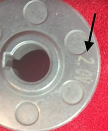
2. Incorrect wheel or wire nozzle chosen. Each feeder wheel has two channels, one large and one small. The width of these channels is written on the opposite side of the wheel to the channel (measured in mm), but is occasionally printed on the wrong side. Check the channel is correct for the wire diameter. If there is a U in the serial number then the wheel is for aluminum. If there is a V, then it is for all other materials.

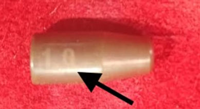
The wire nozzle diameter is printed on the side of the cylindrical portion, measured in mm. Check this too:
3. Incorrect pressure on the fixing knobs. Two red knobs hold the wire in tension in the channels of the feeder wheels. Adjust the pressure by twisting the tops of the red knobs, as demonstrated in the setup procedure video. Tighten the knobs if the wheels are catching, or loosen them if the wire is slipping. The gauge for the pressure is found just under the twistable part of the red knobs, and the pressure on both knobs should be equal.
Note: Excessive pressure on aluminum feeder wire can cause deformation. Inspect the feeding end of the wire to ensure its cross-section remains round. If the wire has been crushed into an elliptical shape, reduce the pressure.

4. Excessively low wire feedrates can increase the relative friction within the tube and exacerbate other wire feeder issues. Gradually increase the feed rate in 5 cm/min increments, up to 70 mm/min, and monitor the issue.
5. Thin or soft feeder wires, particularly aluminum, are more susceptible to bending and catching/spooling. To address this, try re-feeding the wire with the tube kept straight. If the problem persists, consider switching to a shorter tube.
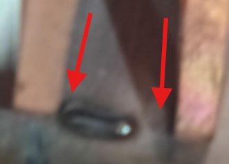
6. The brass nut that secures the feeder tube to the feeder mechanism is touching the feeder wheel. Sometimes the threaded end of the nut can be too long, and will touch the wheel when inserted, preventing it from turning:
Touching (Not Good) comparing with a Gap (Good)


I'm Pressing the Trigger Button, but the
Laser Welder is not Firing
There's a number of minor issues and built in safety mechanisms that could be preventing the laser welding from firing.
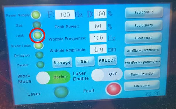
1. The GND clamp is not connected. For the welder to form a proper circuit, the tip must be connected to the ground clamp through a conductive medium, such as a welding table or the workpiece. The "lock" light indicator will illuminate when the circuit is successfully established. Ensure this light is on and stable before starting the welding process.
2. The Laser is disabled. In the main menu screen of the LCD, press the [Laser Enable] slider, and it will turn from off to on.

3. The Emergency Stop is activated. Use the interlocking key to twist the emergency stop anticlockwise to deactivate it.
4. The Laser Power has been set to 0. This is commonly done for testing. To change the power, select [Peak Power] on the main LCD screen, then input the desired power and press [ok]. Remember to press [Set] on the main LCD screen for the changes to take effect.


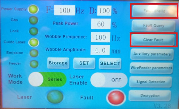
5. There is an alarm preventing operation. The red fault light on the LCD screen indicates that an alarm is active, with the most common being the "no gas" alarm, which signals that the gas is either not connected or the flow rate is too low. To identify the specific alarm, press [Fault Query] to access the alarm list. Use [Next] to scroll through the list until you find the fault that is illuminated. Resolve the fault and continue operation.


Note: If you need to temporarily disable a minor alarm once without resolving the fault, press the [Clear Fault] button. Alternatively, you can disable the alarm and resolve it at a later date by pressing [Fault Shield] and turning off the specific alarm. To proceed, contact LaserWeld NZ for your unique machine password.
Other Weld Defects
The rest of the troubleshooting section is dedicated to welding defects that are not explicitly linked to one of the main four parameters.
There is a Consistent Blob at the Start
and/or End of the Weld Line.
This issue is most common in aluminum welding. It occurs when the feed rate at the start and end is too high for the laser power, resulting in overfill or sections of unmelted wire. Adjusting the feed delay, along with the rise and fall times, will resolve this problem.
1. Press [Auxiliary Parameters] to enter the menu.
2. Increase the Feed Delay in 5ms increments, and press [Set].


Porosity, Oxidization or Smoke at the
Start or End of the Weld Line only
The shielding gas should maintain its set flow rate at all times during welding. However, the flow rate may drop at the start or end of the weld due to a delay between the laser and gas activation, and because it can take time for the gas to reach its full flow rate.
Therefore, the machine has a programmed delay to activate the gas before the laser welder. However, if this delay is too low, gas related defects such as porosity, oxidation and smoke can occur at the start and/or end of the weld line.
To adjust this delay, press [Auxiliary Parameters] on the main LCD screen.

Adjust the laser delay, as well as the gas starting and stopping delays to ensure that the shielding gas begins flowing before the laser starts and continues to flow after the laser stops.
